Turn Your GBA Into a Game Console
By Kon Khanyants
Description
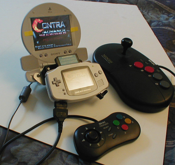
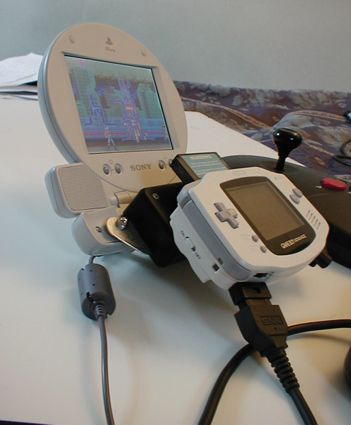
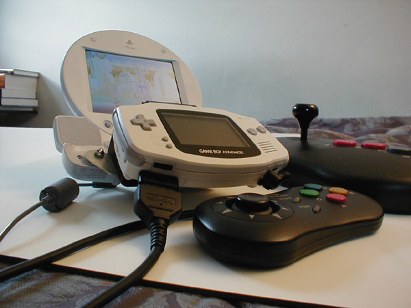
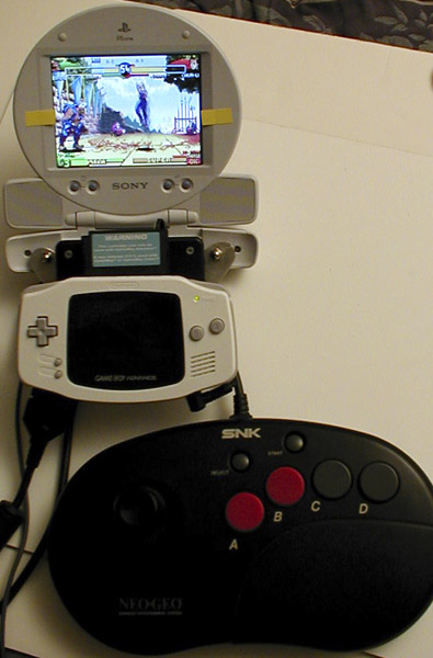
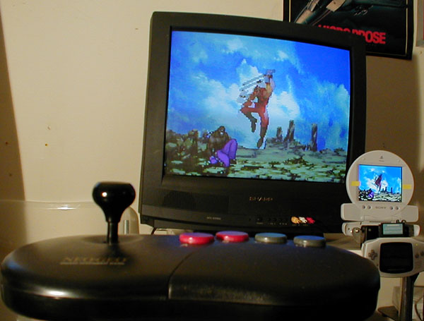
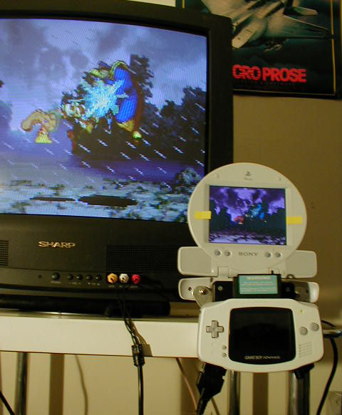
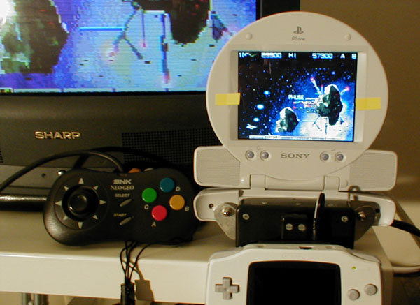
This is a mod of all mods for the GameBoy Advance. Essentially converting it into a game console with an ability to attach a joystick, output video to a TV or an RGB monitor, and provide power management to get around wasting those batteries. The result is amazing and breathes new life into your GBA, even if you only decide to do the joystick mod. The controls feel absolutely different, and some games like Street Fighter Alpha 3 feel very similar to arcade using the four button Neo Geo Joystick controller. For horizontal shooters, the game pad will provide superior control. Contra Advance feels just like the SNES, in fact all games will now give you a feeling of playing on a console. What console would be complete without output to a TV or even better, an RGB monitor. Although a complicated mod the GWGBA is described at the bottom of the page. Using the RGB mod and then connecting to the 5 inch PSOne LCD monitor the picture quality is nothing short of amazing, no blurring, no dot-crawl, discoloration, or other side effects attributed to the low quality connection to TVs. Getting stereo sound from the 1Watt speakers on the monitor is also kewl. The Sony screen is also backlit making the colors extremely vibrant as opposed to the GBASP which is front lit. This is the main reason why it kicks GBASP's butt all up and down the block. The power management mod allows your GBA to work without batteries like a true console, and with batteries when they're available. I also wanted to install the Afterburner but after trying the installation I found the image quality to be sub par, with washed up colors and some very visible lines on the screen. Now you're probably asking, what about just having a Game Cube, VGA cable, GBA Player, and a Hori Gamepad? Well if you're adventurous like me and like a challenge of minimizing design, or if you want to have more control over your games using the classic Neo sticks, or if you still want to keep your GBA portable, or if you just want to make your GBA stand out, then you might want to try these mods. If you're interested in making any of these mods, then read on. You'll definitely need to have some soldering skills and basic electronics knowledge. As always, I won't take any responsibility for the personal injury or harm to your hardware that you might incur attempting any of these mods.
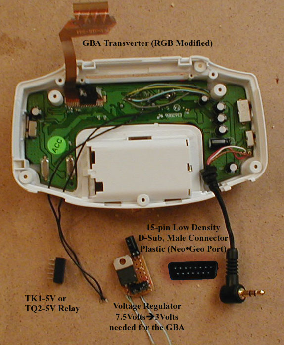
You should note however, that if you attempt any of these mods that you will need to solder wires directly to the GBA motherboard. For the TV output we'll use the GBA Transverter, simply because it is permanently fixed onto the GBA and doesn't come off like the GBA-TV adapter, among other things(which I will explain later). For the joystick port we'll be using a 15-pin Male D-sub connector similar to the one in-use on a Neo Geo game console. I also chose to add a power supply that will draw power from the Transverter and give it to the GBA, because the Transverter did not do this already. It basically bypasses the batteries in the GBA if the wall adapter is plugged in and plugged into the Transverter. It also provides uninterrupted play when switching between the batteries and the power supply, meaning the GBA doesn't reset.
Parts Needed
- GBA Transverter (You don't need to modify it to output RGB like I did but it certainly improves it in the long run)
For Joystick Port Mod:
- 15 pin D-Sub Male connector. I got mine from hacking a Joystick Y Splitter like the one here . It is black and plastic, just what we need. It is a bit difficult to get it out because it is molded in rubber, but I did it with my gator knife.
- 15 wires, better different color ones, about 7" in length each. 28 AWG (gauge) will do nicely. I just hacked an old SCSI cable I had lying around.
For Power Supply Mod:
- TK1-5V Relay. Basically an automatic switch. You can get them from www.digikey.com.
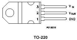
- LD1117V30C 3Volt Voltage Regulator for stepping down the voltage from the Transverter to 3Volts needed by the GBA.
- 10microfarad Capacitor (anything higher will do also)
- 0.1microfarad Capacitor
- Small PCB board from Radio Shack.
- Some insulation tape.
- Multimeter (optional).
|
|
Figure 1. Parts Needed
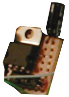
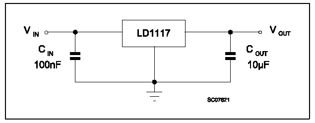
Figure 2. Voltage Regulator Circuit
|
WARNING: To attempt these mods you should be comfortable with soldering and have basic electronics knowledge for your own safety.
Joystick Port Mod
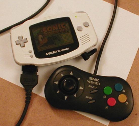
Lets begin. This is the simplest of the two mods, and all it involves is cutting a hole in the GBA Transverter casing and soldering wires from the GBA button points to the 15-pin(Neo Geo) connector itself. I chose to do a Neo Geo based joystick port because I think that they're very comfortable controllers and they're not complex electronically. Each button has a wire as opposed to say SNES joystick which sends out the information using a complicated timing mechanism. The Neo Geo joysticks closely resemble arcade joysticks. Note: If you're building both this and the Power Supply mods then you'll have to make the Power Supply mod first so that the connector would fit in correctly.
1) You can skip this part if you already have a plastic 15-pin D-sub connector. If you haven't already, extract the plastic connector from the Joystick Y splitter by cutting through the male connector's rubber casing. Desolder all the wires and clean up the connector so that only the plastic part remains.
|
|
|
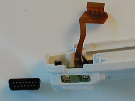
Figure 3. Cut the hole. |
Figure 4. Solder the wires to points |
Figure 5. Insert the connector in the hole |
2) Unscrew and take out the Transverter's motherboard. Cut a rectangular hole in the Transverter as shown in Figure 3. I did this using a hot blade and then filing out the rest of the shape. Make the hole large enough so that the connector fits in. Do not leave any extra room.
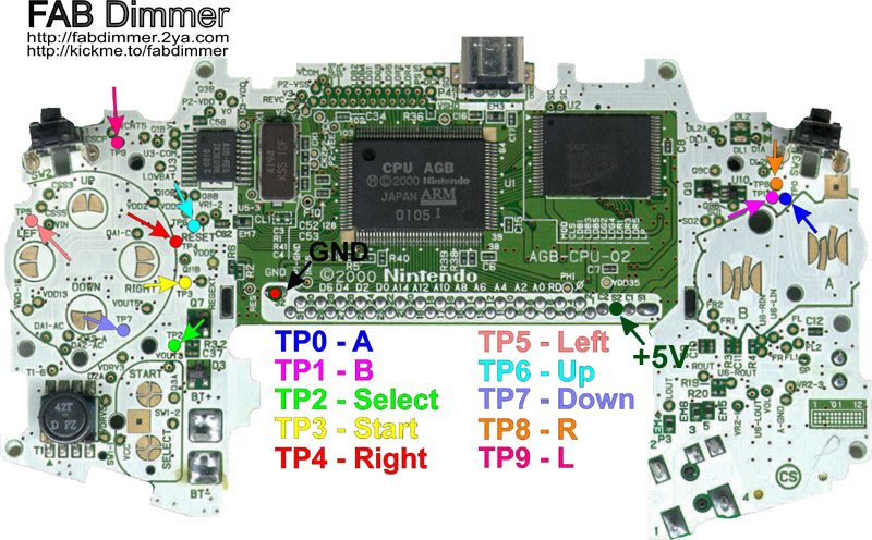
3) Solder the wires from the connector to the test points on the GBA motherboard as shown in Figure 4. Remember that the points need to directly correspond to the buttons on the Neo Geo joypad. The Neo Geo joystick pinout can be found here. You will also need to connect the +5Volt and Ground(GND) lines to the connector. Before you start soldering you should pull the wires through the hole which you made in the Transverter. I have also chosen to make the A button to be B and vice versa on the Neo controller because the geniuses at Nintendo thought it would be great to position their buttons in the B A order instead of the regular A B.
4) Insert the Transverter motherboard back in its place and fasten it with screws.
5) Spread superglue on the sides of the connector which you will be inserting and insert the connector into the hole.
|
Figure 6. Close the casing so that the wires are not damaged. |
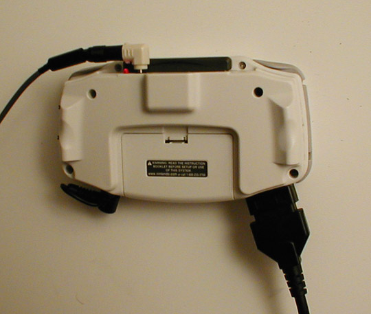
6) Close the GBA case. You will have to do some careful positioning with the wires and see that they don't get cut by any screws or plastic parts of the case or the motherboard.
Power Supply Mod
This is the more complicated of the two mods. It involves building a voltage regulator circuit and connecting it to a relay so that when the Transverter is connected to a wall power adapter and is turned on, it supplies power to the GBA, bypassing the batteries, thereby conserving battery life. The power supply itseld is just a 7.5Volt power adapter capable of delivering around 1500mA, just like the one which comes with the Sony PSOne LCD. I feel that the Transverter should have somehow accomplished this task by itself like the GBA-TV adapter did, but no biggie, we can build our own. Using this mod you can play the GBA using batteries or the wall adapter and switch between the two without resetting the GBA. To switch to the external power mode you just have to turn the Transverter on, and the relay does the rest. There are two parts to this mod. Let's begin. Note: If you're building both this and the Joystick mod, you'll have to do this one first.
Building the Voltage Regulator Circuit:
Building this circuit is fairly easy, and should take about an hour.
|
|
|
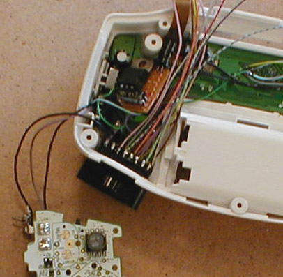
Figure 7. Photo of the circuit |
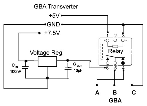
Figure 8. Schematic of the circuit. |
Figure 9. Pins of the regulator chip. |
This is fairly straightforward. Just solder the connections according to Figure 8. Don't worry about Vin, Vout, and Ground for now, just complete the circuit so that it looks something like in Figure 7. You'll need a small and compact design since you want to fit it into a very small space between the GBA and the Transverter.
Connecting to the Transverter:
Now you need to connect the voltage regulator circuit which you just built to the Transverter.
|
Figure 10. Connect the voltage regulator to the Transverter |
In Figure 10, point (A) is the 7.5Volts which you get from the power adapter. You will connect this to the Vin of the voltage regulator and it will in turn convert it to 3Volts suitable to power the GBA. Point (B) is the ground and you need to connect this to the voltage regulator's ground points. Note the positioning of the regulator circuit and the relay. It is the only way by which they would fit into the case. When positioning the voltage regulator, you will need to put insulation tape between it and the Transverter board. Also, I actually crazy glued the relay to the Transverter board after I soldered all the wires to it so that it would not become loose. You may or may not do this depending on your preference.
Connecting to the GBA:
|
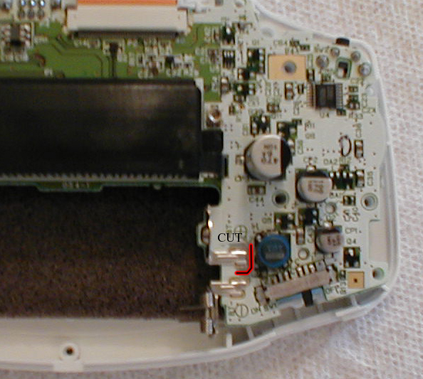
Figure 11. Cut the lead around the +3V battery receptacle. |
1) To bypass the batteries, you must cut the copper roads from the battery to the GBA circuitry on the motherboard. I did this using an X-Acto knife. You'll first need to take off the layer of white paint that is around the road. Then keep sliding the knife on the road until you have cut it into two and the two sides don't touch(you can check this using an Ohm-Meter) as in Figure 11.
|
|
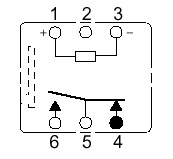
Figure 12. Solder wires to these locations. |
Figure 13. Relay schematic. |
2) Now you need to connect everything together. Solder the wires to the points indicated by the red dots. According to Figure 12, (A) goes to the relay pin 4, (B) goes to the relay pin 5, and (C) goes to the Ground on the Transverter or the voltage regulator circuit. It is difficult to see in the picture but point B is actually before a small resistor which leads to the main switch on the GBA. Solder one end of the wire to the 6th pin on the relay and connect the other end to the Vout on the voltage regulator circuit.
3) Since the Relay needs +5Volts to function, the middle of this page explains how to get +5Volts from the Transverter. You need to then connect it to pin 1 on the relay. That's it, you may now perform the joystick mod or connect the Video portion of the Transverter and close the GBA and enjoy the battery-less experience.
|
|
Figure 14. Everything connected now. |
Figure 15. Here's the full schematic of all the connections. |
Some Info on RGB Mod and the GWGBA
|
|
|
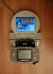
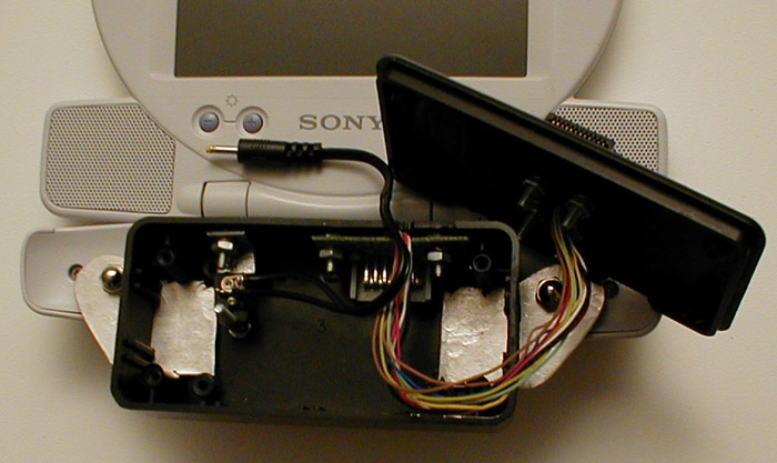
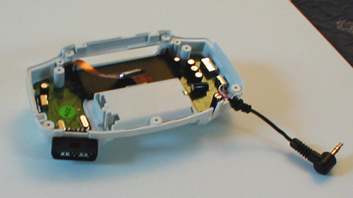
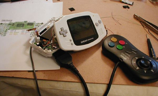
Figure 16. GWGBA in use and disassembled |
As you can see in the whole picture, there's also a Sony PSOne LCD monitor attached to the GBA console. This is accomplished through the use of my own creation called GWGBA. I will not go into extreme detail of how to make one, but I will provide a photo of the insides, and it should be clear enough from the photo above that it is a simple adapter with no circuitry. Suffice enough to say that it requires you to break apart another Transverter and gut it for the PSOne AV connector because they are non-standard connectors. Positioning the connector is not simple since you have to measure exactly where the port on the monitor is. Then, you need only to connect the wires from the cable AV plug to the AV out port. Of course if you also want to route power to the Transverter, you will need to do the same for the 4.75mm power plug. The pinout of the Playstation AV connector can be found here.
The Transverter's RGB mod is used so that the image could be displayed on a Sony LCD monitor in superior RGB quality. Info on the RGB mod can be seen in the middle of this page.
Note: This page is provided for information purposes only. It is not affiliated with Nintendo or any other company whose products are mentioned on this page.
Any feedback is welcome to kon@konlabs.com
Back to Main

FastCounter by bCentral
|


.jpg)